Alabama Szer Kft.
Project implemented
Farkas Kertészet - 1000 m ³ buffer tank on seat
At the seat he built a 1000 m ³, standing, heat-insulated buffer tank Alabama Szer Kft. for horticultural use.
- Year completed
- 2026
- Site
- Üllés
- Work completed
- Tank construction
For the planting garden site, it built a buffer tank with a nominal capacity of 1000 m³, standing and heat-insulated at the Alabama Szer Kft. The construction of a tank in 2026 included the implementation of a steel tank with a diameter of 11,3 metres and a height of 11,52 m. The work was carried out in full, from the construction of the on-site tank body to the heat-insulated, outlying state. The investment was linked to the heat storage task of the gardening plant.
Gardening heat storage at the planting site
The focus of the seating was a large buffer tank. The gardening storage is one of the separate equipment of the service heat supply: it has a large water space to store the heat. The Alabama Szer Kft. the task of implementing this tank-building worker. The standing design, thermal insulation and steel tank body together determine the nature of the finished installation.
The tank was made in connection with the investment of the gardening site. In this environment, a system is needed that operates between heat supplies and use, where storage has its own role. The construction of a tank is thus a well-defined construction task resulting in the heat storage capacity for horticulture. The work has taken together from the assembled tank body to the heat insulated and encased design of the installation areas.
The storage role of horticultural heat supply
The heat demand for gardening heating is developed together with changes in use and external conditions. The heat production and the instantaneous need for use may differ. The buffer tank provides a space of water in which heat can be stored and then used in order to function the system. This temporal link is the fundamental importance of heat storage in hot water systems.
The nominal volume of 1000 m³ at the planting site gives the storage scale. From the garden, the container is part of the operating background related to the heat supply system. However, it is the implementation of a large steel structure with a large diameter on the ground from the contractor's side. Together, these two views make investment understandable: the storage capacity needed for the operation of the system had to be built in the garden area.
On-site tasks arising from dimensions
The tank is made with a diameter of 11,3 metres and a height of 11,52 metres. Its nominal storage capacity is 1000 m ³. These data indicate the space extent of the tank and the scale of construction on the spot. The vertical cover and the construction of the related roof structure are the installation tasks reported at several different points in the working area, both in areas close to the terrain level and at higher connections.
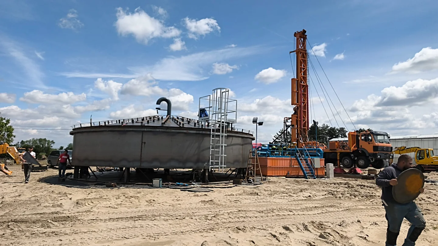
When the large container is carried out on-site, the movement of structural elements, the assembly and the approach of the workstations must be aligned. The area around the tank body is part of the construction: here are the prepared elements, the equipment used for installation and the connecting working areas. This actual on-the-spot environment had to be used for the installation of the seating tank to achieve the task undertaken.
Reception structure and foundation work phase
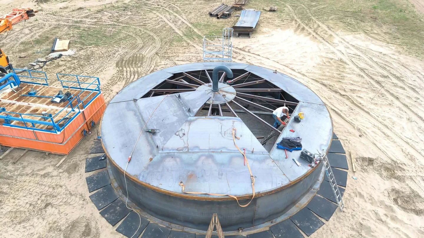
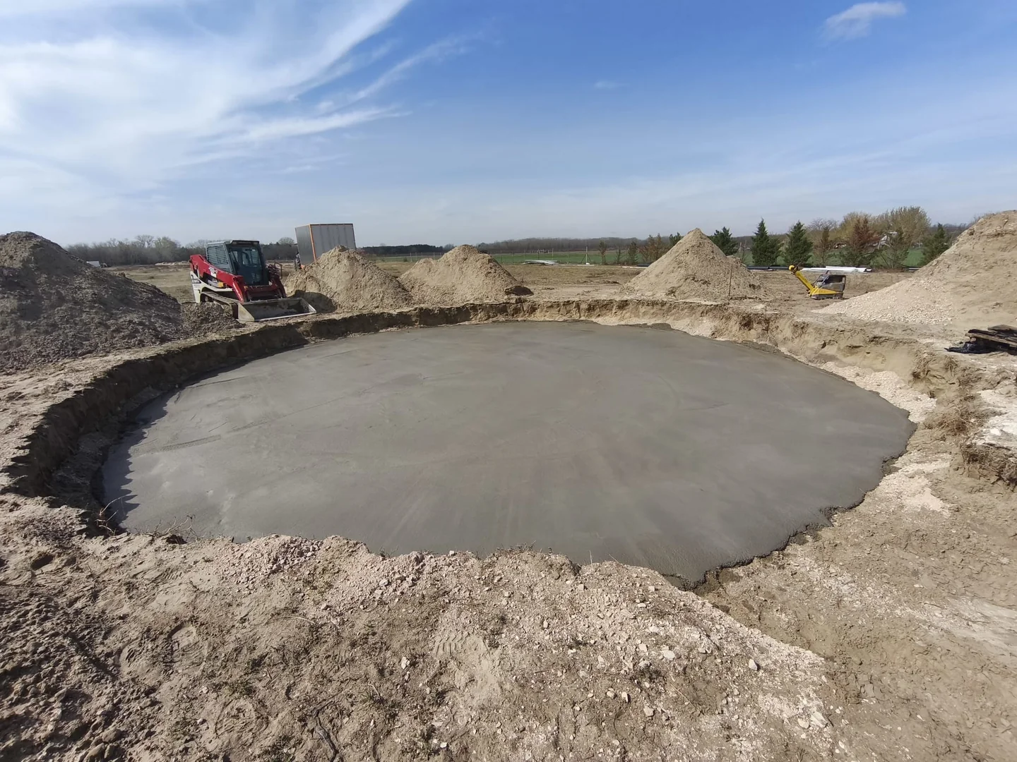
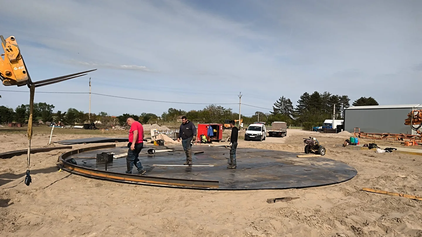
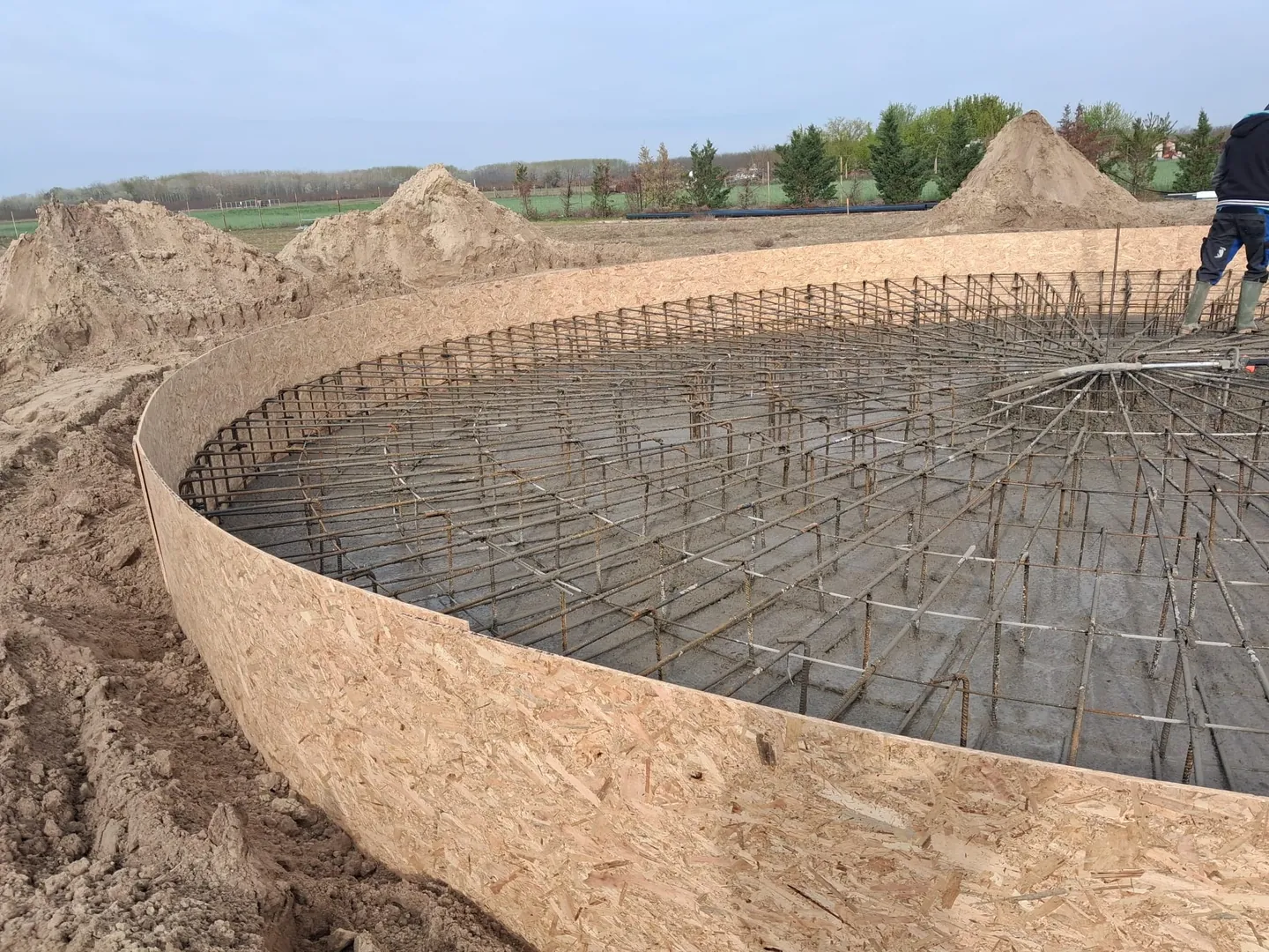
One of the early stage conditions for building the tank was the design of the round floor. In the seating area, the shutter, steel linings and concrete surfaces are also present in successive condition. The tank body was assembled at this reception level. The large circle layout has already defined the location and extent of the tank before the installation begins.
In the event of a meeting of the reception structure and the steel tank body, the various tasks of the construction are linked. The environment of the building is still open, and the walls and external fittings of the tank are later displayed. The meaning of such working phases can be seen in the relationship of interconnected structures: a properly prepared space for tank construction and a coordinated on-site continuation is required.
Compilation of bottom plate and tank cover
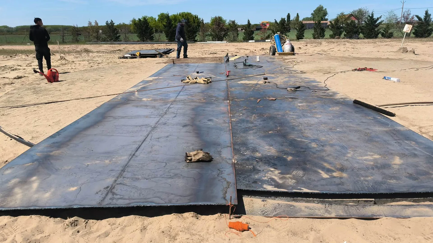
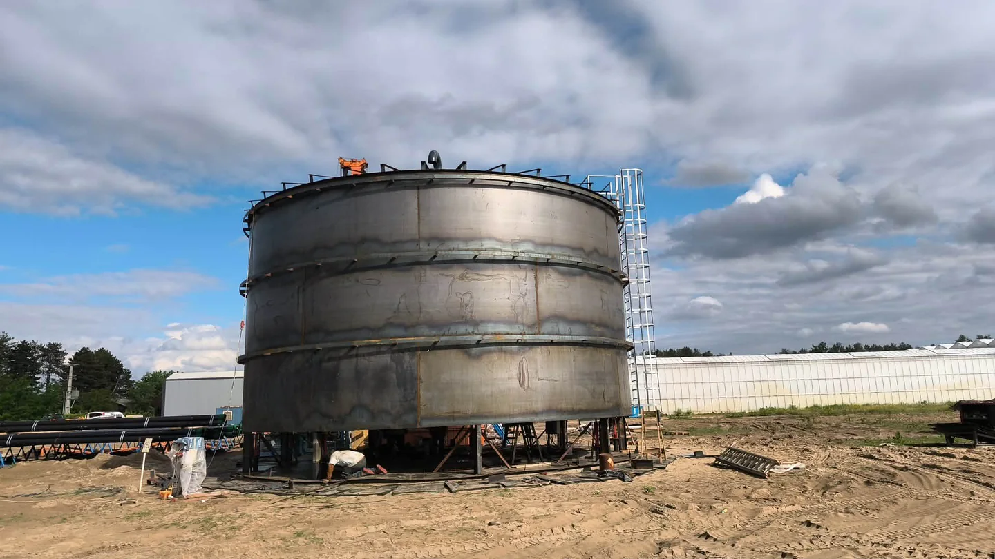
During the on-site assembly, the tank water was formed from steel bottom plates and vertical covering sections. The cover forms the side wall of the tank body; it forms the large water space from the matching plates. During the installation on site, the tank body gradually became a dominant building at the gardening site. The structure in this condition is visible without the outer hull.
The design of the circle and the vertical design together determine the installation environment for the coating. The outer side and the inner space of the container provide different work positions, while the same steel structure is made of parts. The Alabama Szer Kft. the construction of tanks has been carried out by these related on-the-spot tasks up to the assembled tank body. Intermediate conditions detect structural work behind the finished heat storage.
In the tank body, the bottom, the cover and the top seal together limit the storage water. The relationship of each part is therefore a major structural issue of the container as a whole. Behind the finished outer surface, these matching steel parts give the body of the device. During the construction of the cover, the assembly of large plate surfaces and local connection points will lead to the same result: to achieve the tank space used for subsequent heat storage.
Sugaras roof structure above the tank
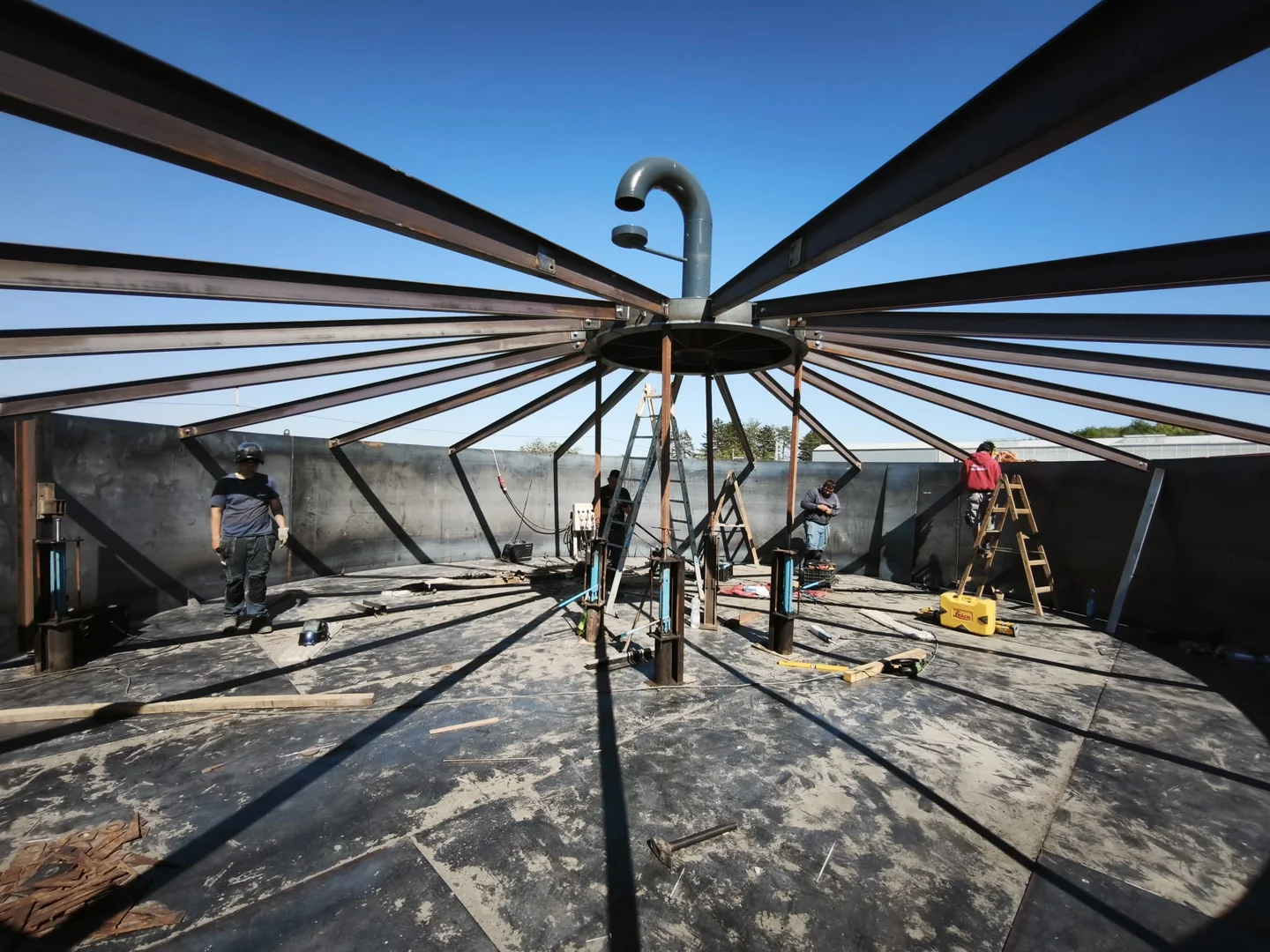
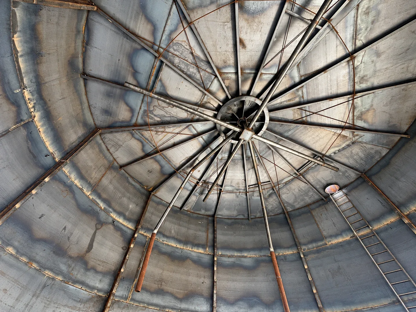
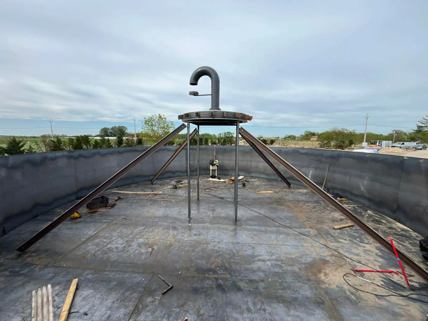
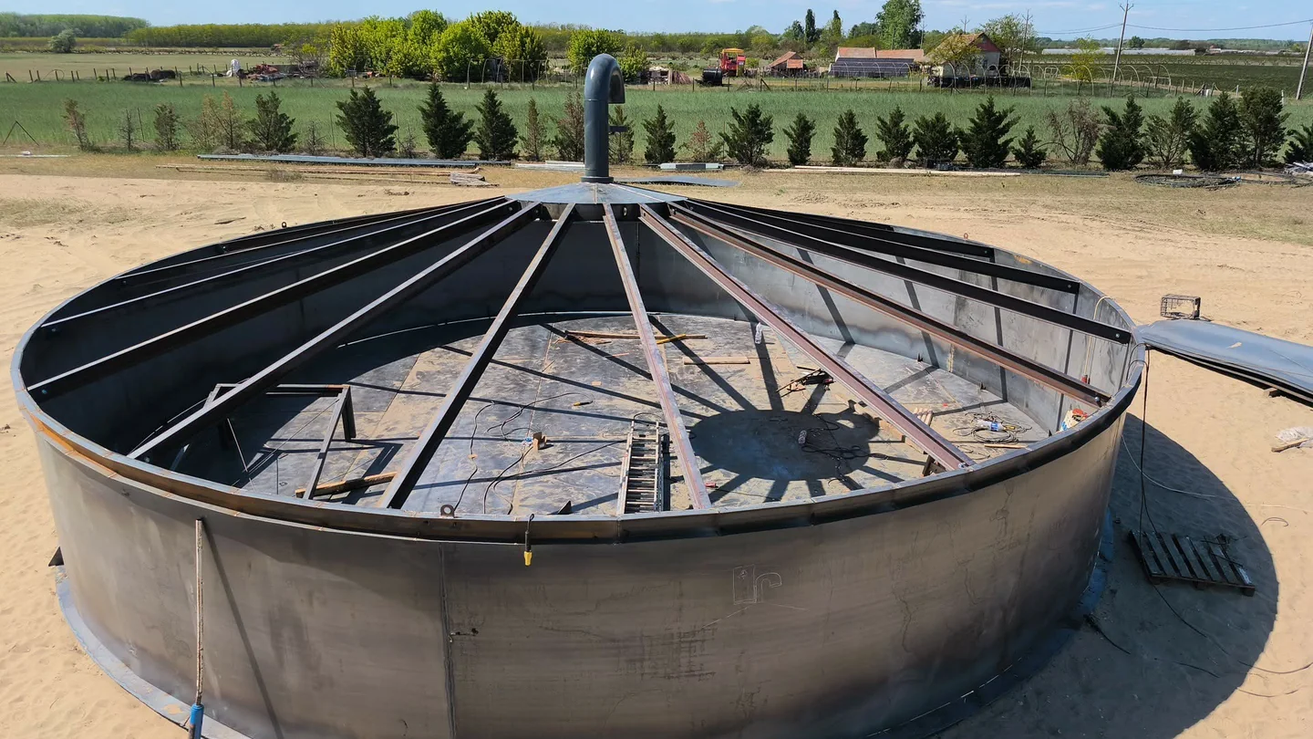
A roof structure built on beam supports was built on the top of the tank. During installation, the supports can be seen before the cover is installed and then in the intermediate condition of the roof plates. The roof is linked to the top closure of the tank body, so the cover and the contact of the upper structure is a separate working area for tank building. The interior view also shows the spatial order of the large structure.
The container roof assembly also gave a service from the upper workpieces and the inner space of the tank. In the seating operation, the roof supports, the cover and the covering were made as matching structures. After the roof was formed, the appearance of the tank body was also getting closer to the final form. This was followed by additional workplaces in thermal insulation and covered design.
Heat insulation and outside coating design
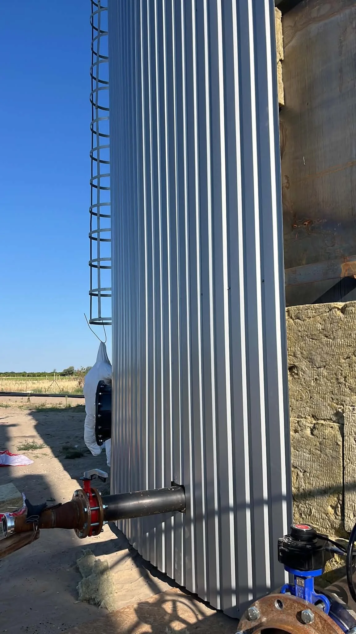
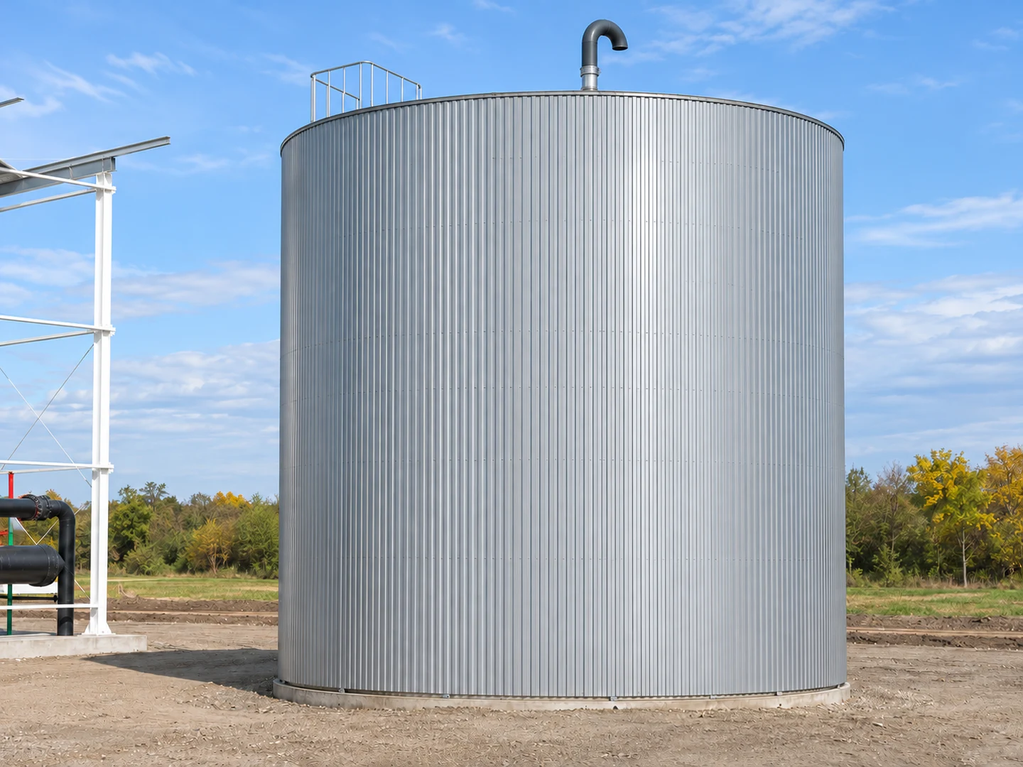
The seating buffer container is made in heat-insulated design. The outer side of the container is connected to the thermal insulation by a layer of hull. The two layers have different additional functions: insulation reduces heat transfer to the environment, and the outer surface provides a finished surface in the container environment and external protection of the layers. The site design also included the assembly of these layers.
In the large heat storage, the cover, roof and connection environment form an outer surface. The related design should therefore continue at different structural points. The seating container is already in a uniform appearance on the garden work area after the cover has been finished. However, behind the finished casing remains the steel tank body assembled on the spot and its heat storage function.
Connections to the outer side of the container
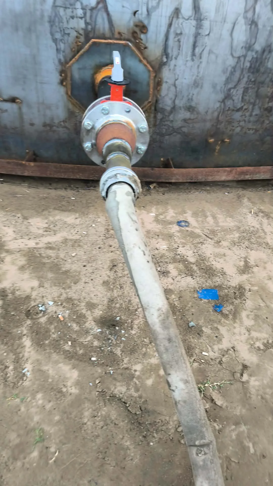
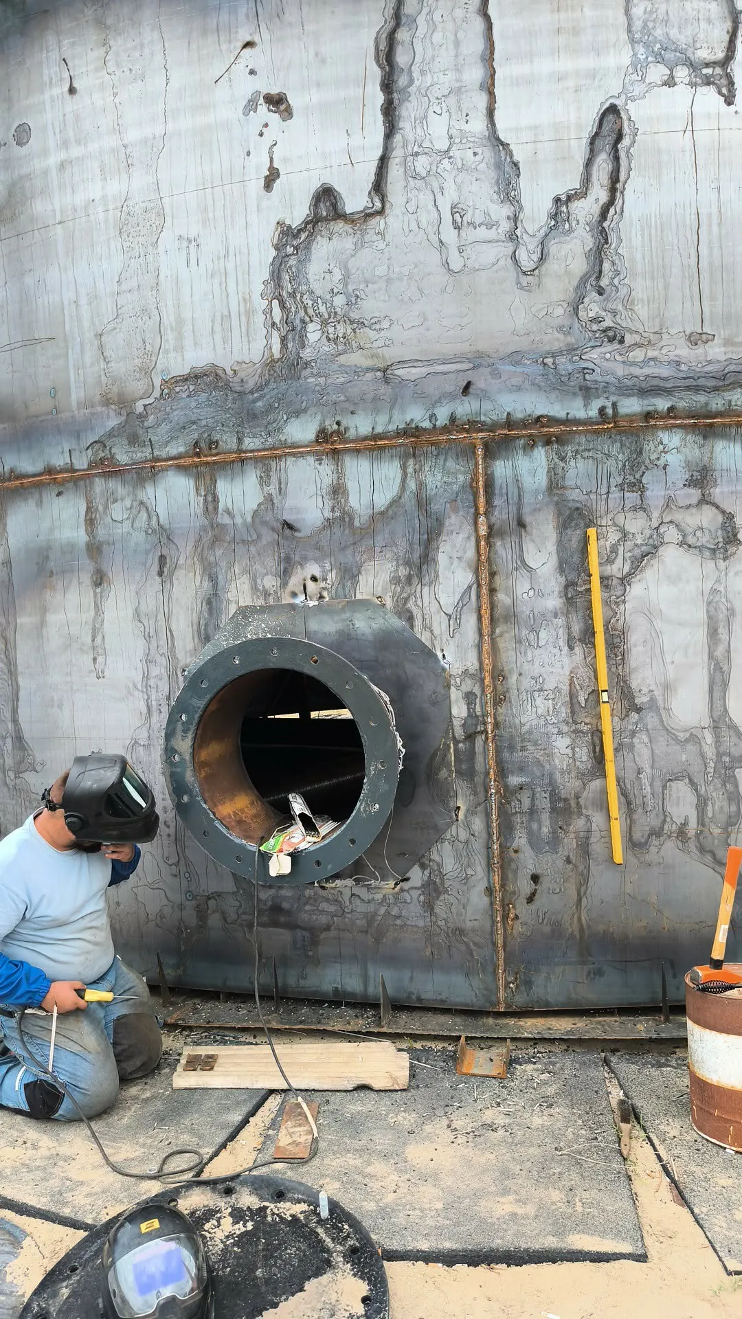
The tank has mechanical connections. The installation of a tank stump, external connection and connection with a fitting are included in the seating phases. In these places, the storage tank body meets the mechanical elements in its surroundings. In addition to the large, interconnected surface, smaller, independent mounting spaces are created.
The location of the points of accession is also relevant for future use. The tank is involved in the operation of the system as part of the gardening heat supply via the related wires. The meeting of the external surface of the pipeline, assembly and container shall be adjusted to the actual installation site. The large structure and these local mechanical details were part of a joint construction task in the seating tank construction. The storage site at the site also determines where the tube sections leading to it meet and how to access the external interfaces.
Heat storage capacity and operational use
The nominal volume of 1000 m ³ indicates the size of the storage water. The amount of heat that can be used is also affected by the difference between operating temperatures in addition to the water. The container should therefore be interpreted together with other elements of the heat supply system: storage, heat transport and use are related tasks. In a garden, these relationships are based on the daily operation of heating.
For the investor, the implementation of the heat storage facility means an extension of the engineering background of the site. The result of the construction is a finished container with a specified volume, which provides space for the heat storage task. This capacity had to be developed in the planting project in the real work area, in the context of the related construction. The completed structure can thus be interpreted as an investment element related to the operation of the horticultural plant.
Storage also means a temporal task. The evolution of the heat demand is influenced by the use of horticulture and the weather, so the relationship between different times in the heat supply has a role to play. The water space available in the tank serves this system-level task. From the point of view of the site, the storage is thus linked to the equipment that gives the background to the daily plant and is designed as a large, independent structure.
Access and subsequent maintenance
A tank will be permanently present after it has been completed. Therefore, subsequent access to the environment should also be considered: external fittings, connections and points used for inspection should remain available. The working space around the tank and the arrangement of the associated wires will also be used. The maintenance of the heat storage is therefore part of the operation of the mechanical system.
The external status of the encased container and the environment of the connections may give different tasks to the operator. The transport links between the surfaces, the accessible fittings and the site determine how to approach the necessary work together. The seating reference shows the container in this gardening context: a large heat storage, the structure and mechanical connections of which serve everyday operation.
Work area of the tank and related construction
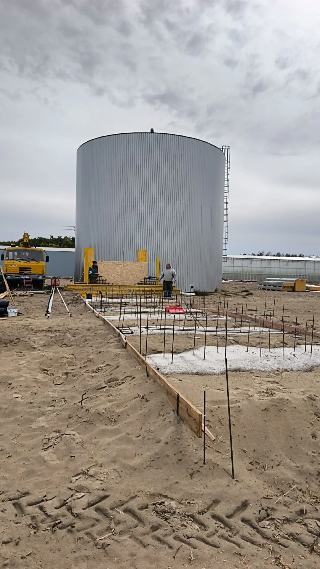
Other parts of the horticultural investment are also visible around the heat-storage tank. The tank is already clad, while the surrounding work area shows further construction stages. These views show how a standalone mechanical installation fits into the evolving site. Installation, material handling and subsequent operation use the same area in different ways.
In our tank construction work, our own task had to be done among the capabilities of this site. The finished tank body, roof, thermal insulation and hull are built-in construction elements. The actual location and size of the container for the work in their environment have given an interface. The planting project therefore means both the construction of the large steel tank on site and the implementation of the garden work area.
Fully completed tank construction task on seating
Alabama Szer Kft. completed the agreed buffer-tank construction work in full at the horticultural site in Üllés. Completed in 2026, the upright steel heat-storage tank has a nominal capacity of 1000 m³, a diameter of 11.3 metres and a height of 11.52 metres. Its thermal insulation and external cladding form part of the completed tank. The photographs follow its construction stages from on-site assembly to the clad appearance.
This investment is one of our experiences with the construction of large tanks for horticultural heat supply. The essence of the result is that a heat storage actually built in the prepared work area was created. The construction and engineering workplaces are connected by means of equipment which provides the storage space undertaken for the heat storage task of the planting site.
Seating buffer tank and construction working phases