Alabama Szer Kft.
Completed project
1000 m³ thermal-water tank and heating plant in Szentes
In Szentes, we built an insulated 1000 m³ thermal-water storage tank and the associated heating plant.
- Year completed
- 2023
- Site
- Szentes
- Work completed
- Tank construction
At Bereghát in Szentes, Alabama Szer Kft. built an insulated 1000 m³ thermal-water storage tank, the associated heating plant and an insulated steel pipeline supplying heat to a greenhouse and industrial-building complex. Steel tank construction, pipework and pump installation formed one coordinated construction scope.
Heat supply for a horticultural complex
A greenhouse development needs a heat supply as well as growing space and service buildings. Heat must reach its users, and the central equipment must connect to heating systems elsewhere on the site. In Szentes, the tank, heating plant and connecting pipeline provided that link.
The 1000 m³ tank provided storage within the thermal-water system. The associated mechanical equipment served water transfer and distribution. The insulated steel pipeline supplied the greenhouse and industrial-building complex, extending the work beyond the immediate tank area.
The three parts needed coordinated connection points. The tank location, space for the pipe assemblies and the pipeline route together determined how the site heat supply was connected.
Our contracted tank and mechanical installation scope
Alabama Szer Kft. carried out the work. Our scope covered the insulated 1000 m³ thermal-water tank, its heating plant and the insulated steel pipeline for the heating supply. We completed this contracted scope, coordinating tank construction with the associated mechanical installation.
Fabricating the tank from steel plates and assembling pipework with pumps and fittings required different skills. The tank work centred on positioning and joining large plates; the mechanical work focused on pipe branches, shut-off valves and equipment connections.
Connecting pipework brought the two work areas together. The tank construction and heating-plant installation therefore had to progress in coordination. Material handling and access to each installation area also shaped the site work.
What does the 1000 m³ storage capacity mean?
Storage capacity describes the volume of water the tank can hold. In a thermal-water heating system, this stored water connects to the pipework and equipment serving the users. The 1000 m³ capacity was a defining specification of the tank scope in Szentes.
Water carries heat, absorbing or releasing energy as its temperature changes. Storage is therefore part of the thermal-water heat supply. The tank and heating plant must bring together the water route, equipment connections and onward supply.
External insulation reduces heat transfer between the stored water and the surroundings. Because the tank stands outdoors, its insulated construction forms part of the thermal design. The outer cladding protects and finishes that insulation layer.
Bottom plate and lower shell course: the start of site assembly
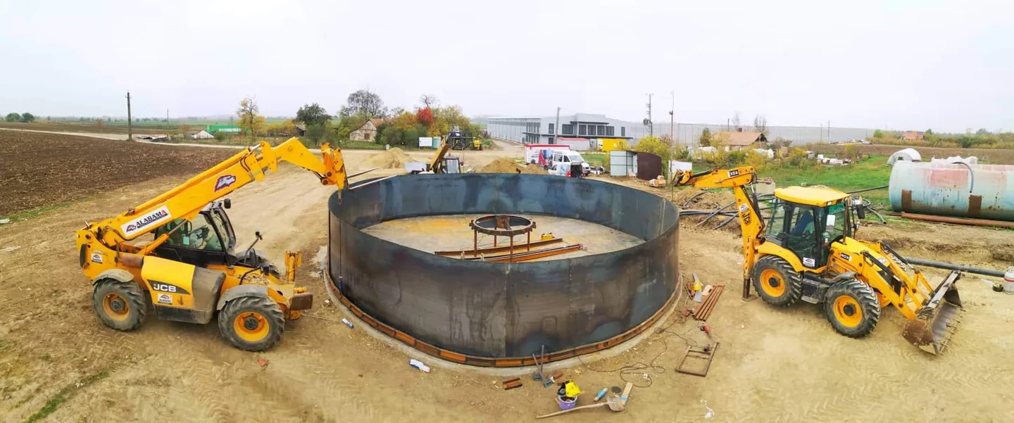
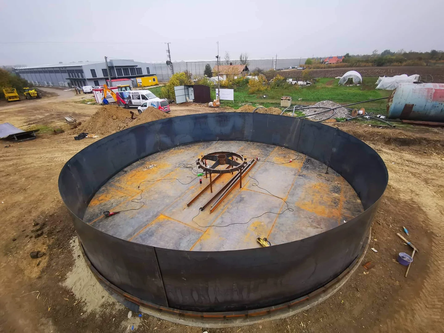
The early site assembly established the bottom plate and lower shell course. Plates arranged around the circular plan form the tank wall, while the bottom plate closes the base. Aligning these components provided the starting point for the rest of the structure.
Handling and holding the large plates in position was part of the assembly work. The adjoining plate edges and the circular shell had to be aligned together. Installation tools and site machinery supported positioning, access and preparation for the next stages.
At this stage, the assembled components were still close to ground level. The roof frame was also assembled at this working level, so the shell and upper structure developed through connected site operations.
Radial roof frame and roof plating
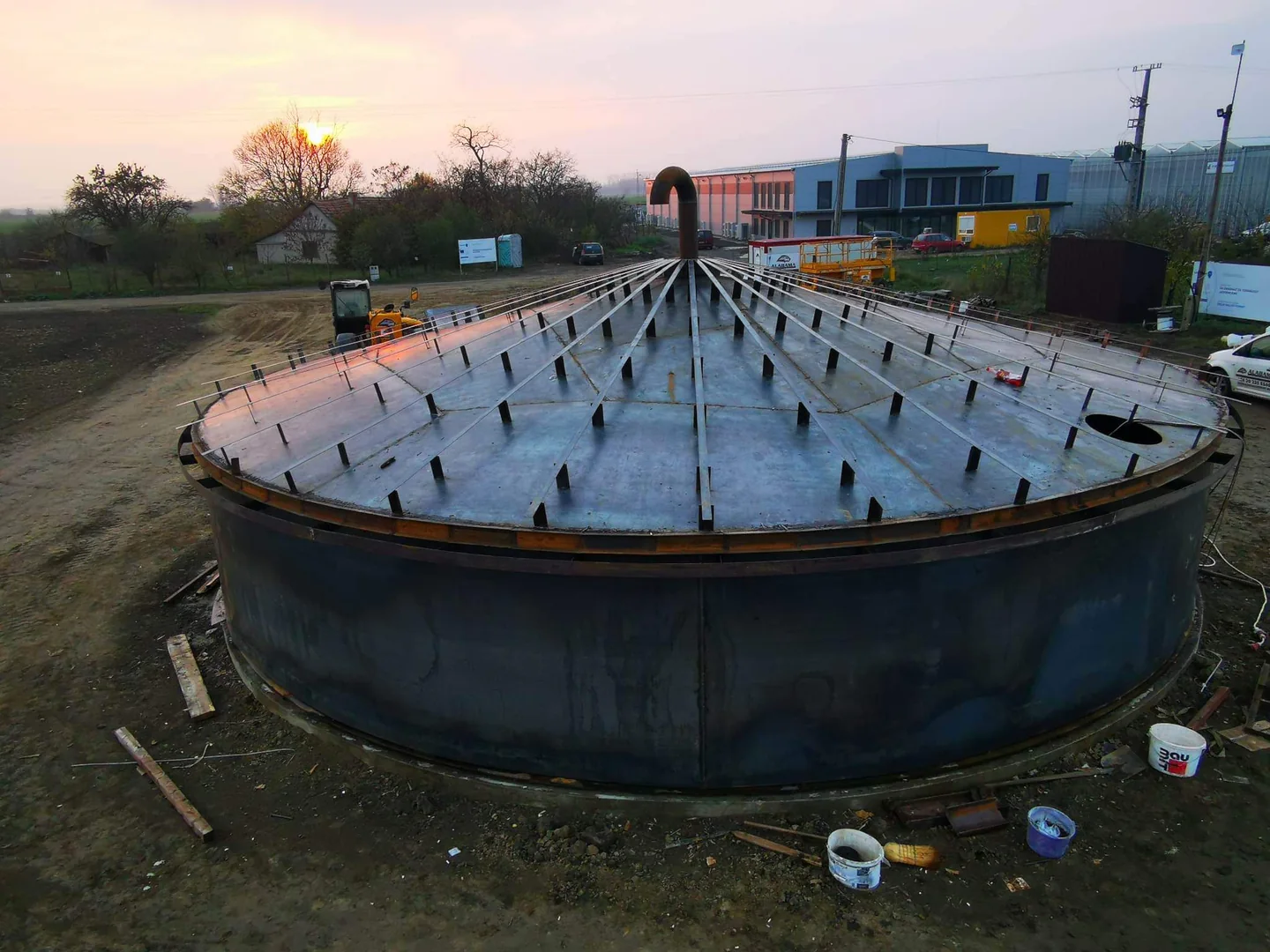
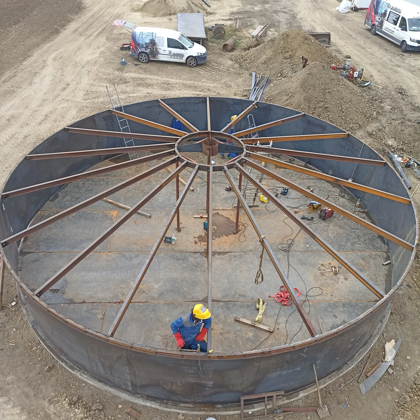
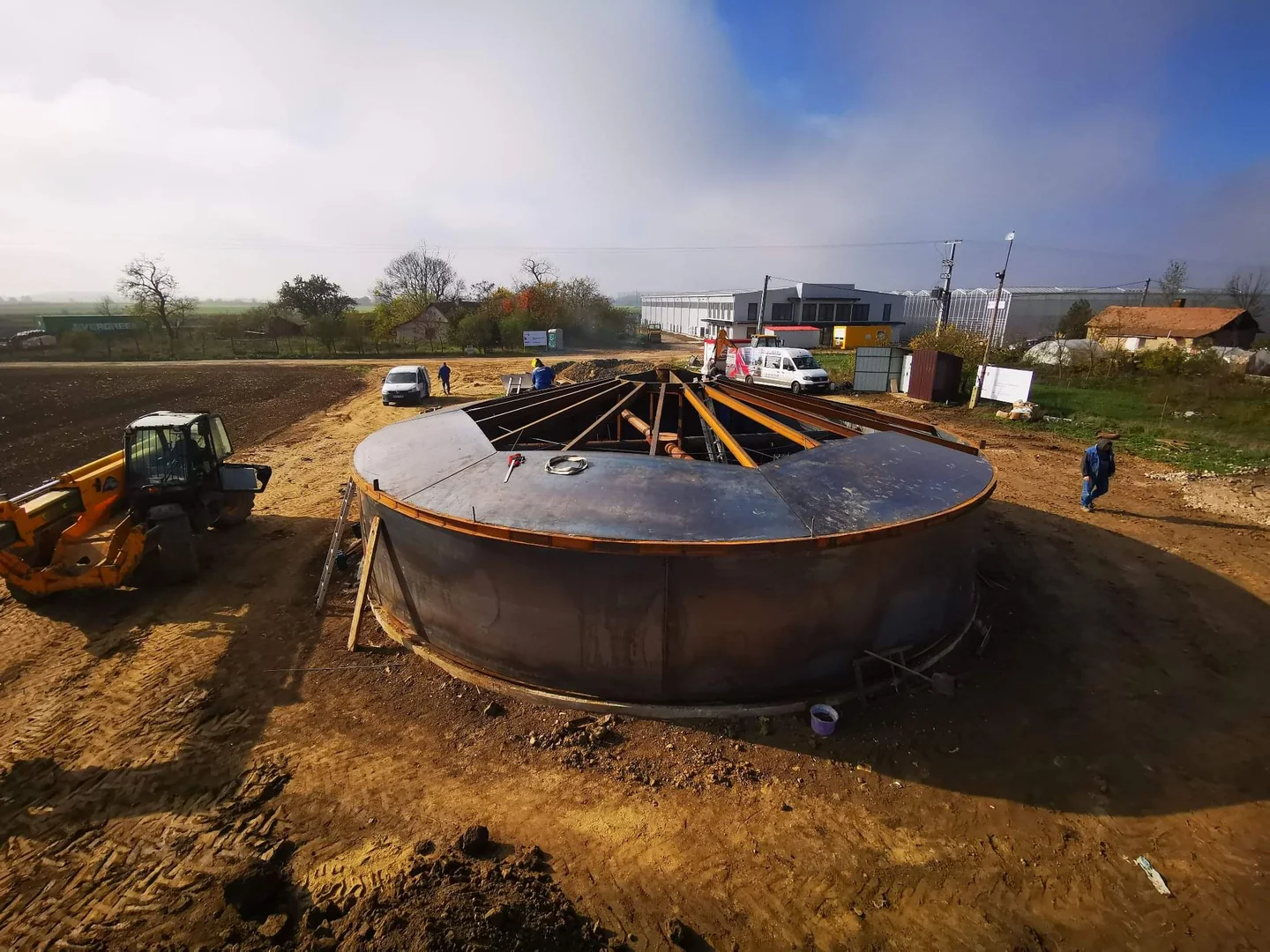
Steel members running from the centre towards the shell formed the roof support. The radial frame carries the roof plates and connects the centre to the perimeter. During assembly, the members had to align with one another and with the circular shell.
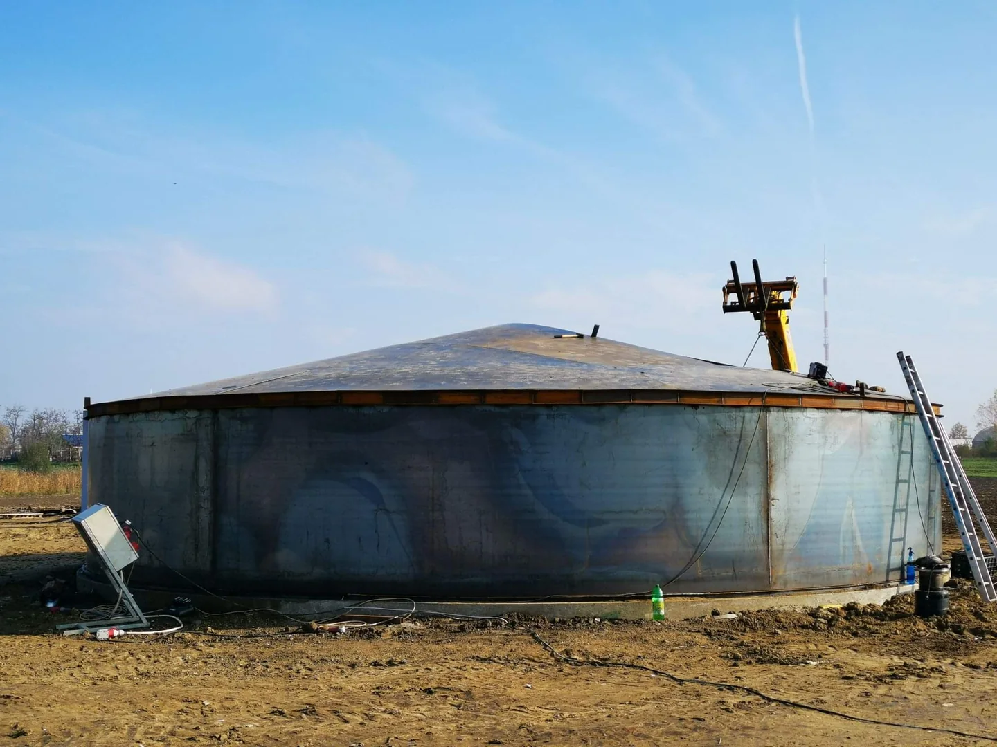
Roof plating followed frame assembly. The roof was initially only partly covered, before the continuous, gently conical upper surface took shape. The plate joints and their connections to the structure had to be formed together.
The tank roof is a large steel structure. Its plates, supporting frame and shell must work together as an assembly. Completing the roof and continuing the shell construction brought the tank towards its full height.
Building the shell to full height
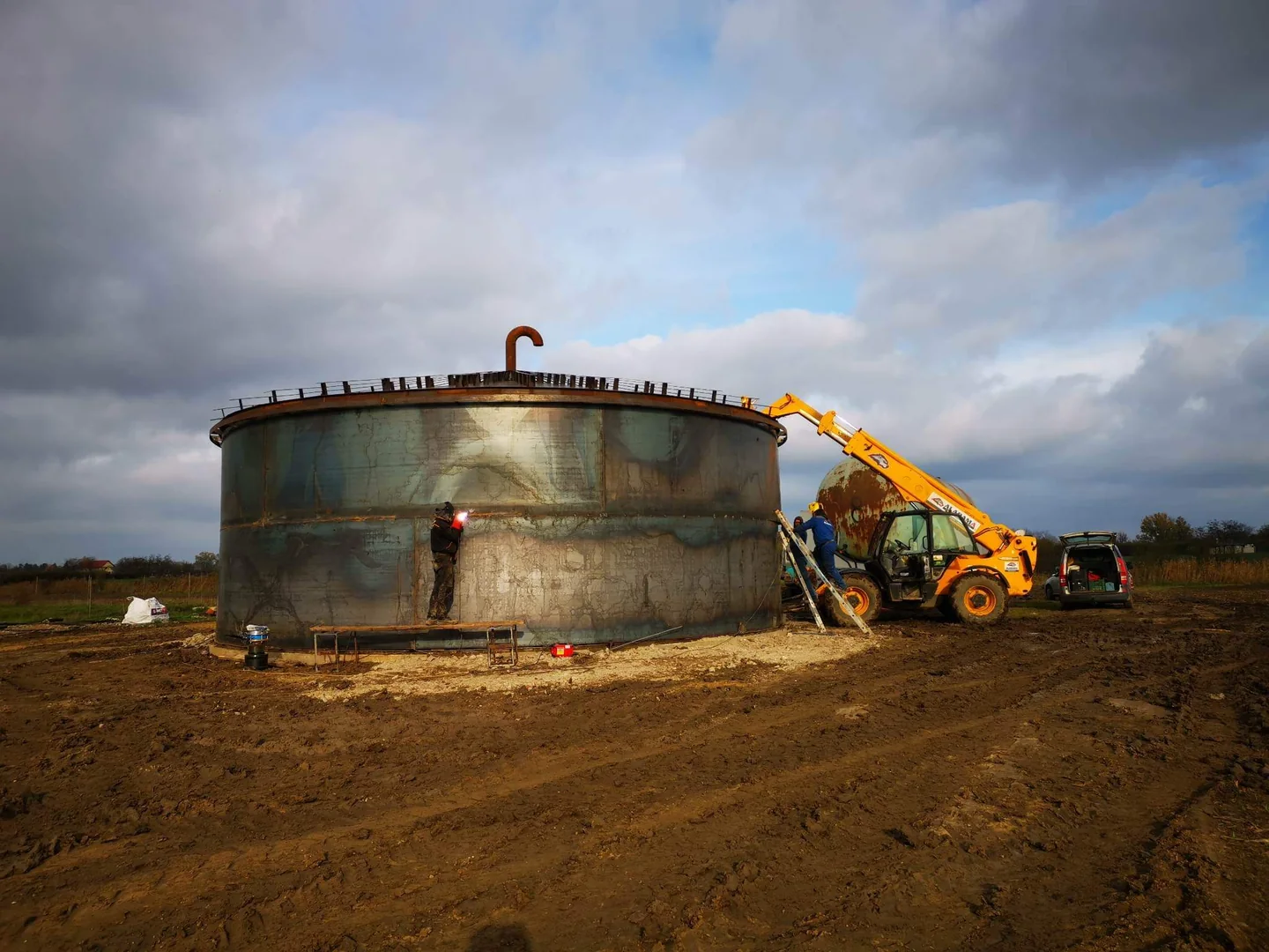
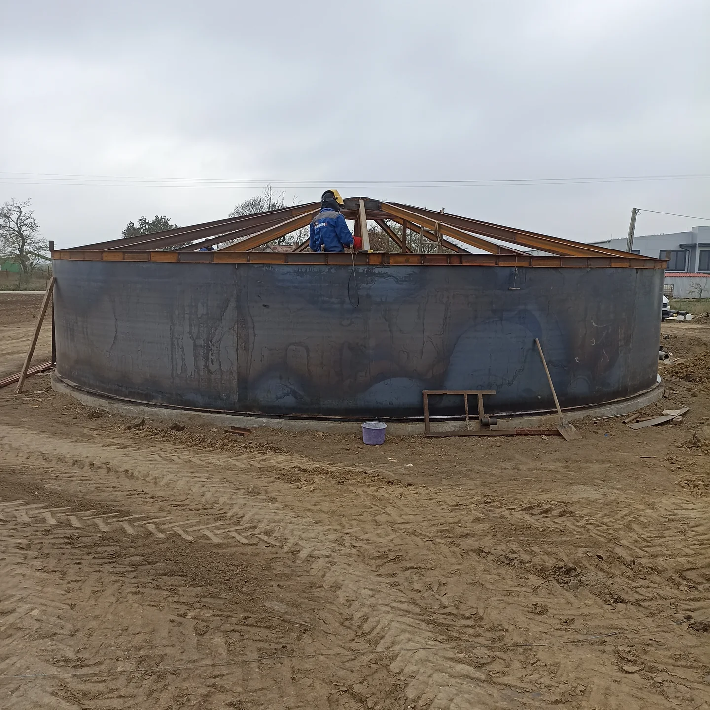
Further construction added the higher shell courses. The horizontal courses form the cylindrical wall one above another. Site work involved positioning and aligning the plates and making their joints, alongside the roof and previously assembled components.
Work on the full-height tank needed different access from the first, low shell course. Access to components, work along the wall and material handling had to adapt as the structure grew. The external access ladder was also incorporated into the developing tank.
The steel shell reached full height before the external cladding was finished. At this stage, the relative positions of the cylindrical wall, roof and mechanical connections could be seen clearly.
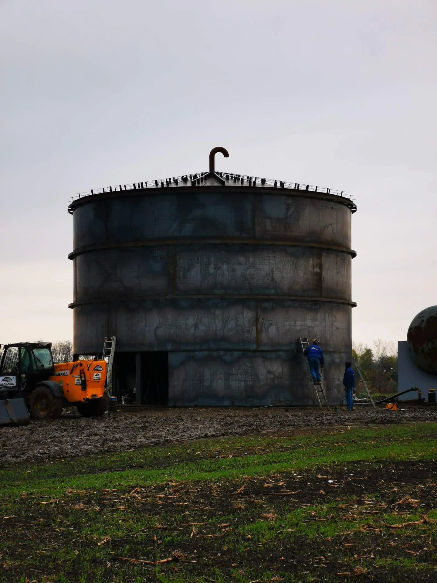
Plate joints and assembly of the large steel surfaces
The tank bottom, wall and roof use steel plates in different orientations. Bottom plates form a flat surface; shell courses follow the circular plan; roof plates follow the supporting frame. Each requires its own positioning and joining work on site.
The plate joints follow a defined arrangement across the large surfaces. Circumferential joints between shell courses and vertical joints between plates together form the tank wall. The plates must be positioned before welding, with assembly coordinated around the adjoining components.
Bottom, shell and roof assembly therefore brought several different tasks together in Szentes. Beneath the eventual cladding, these large steel surfaces form the tank structure. Many individual pieces had to become one continuous tank body.
The heating plant beside the tank
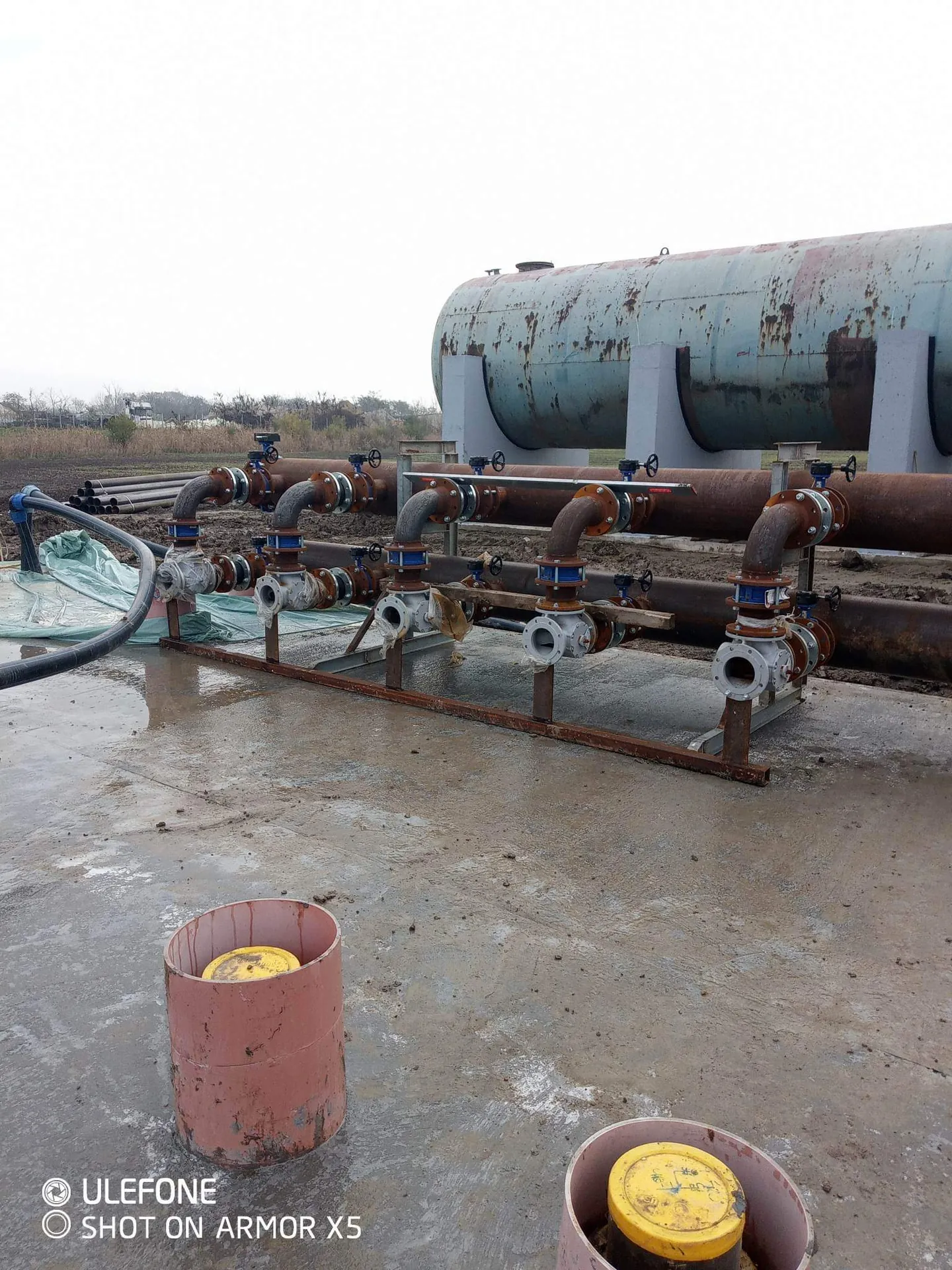
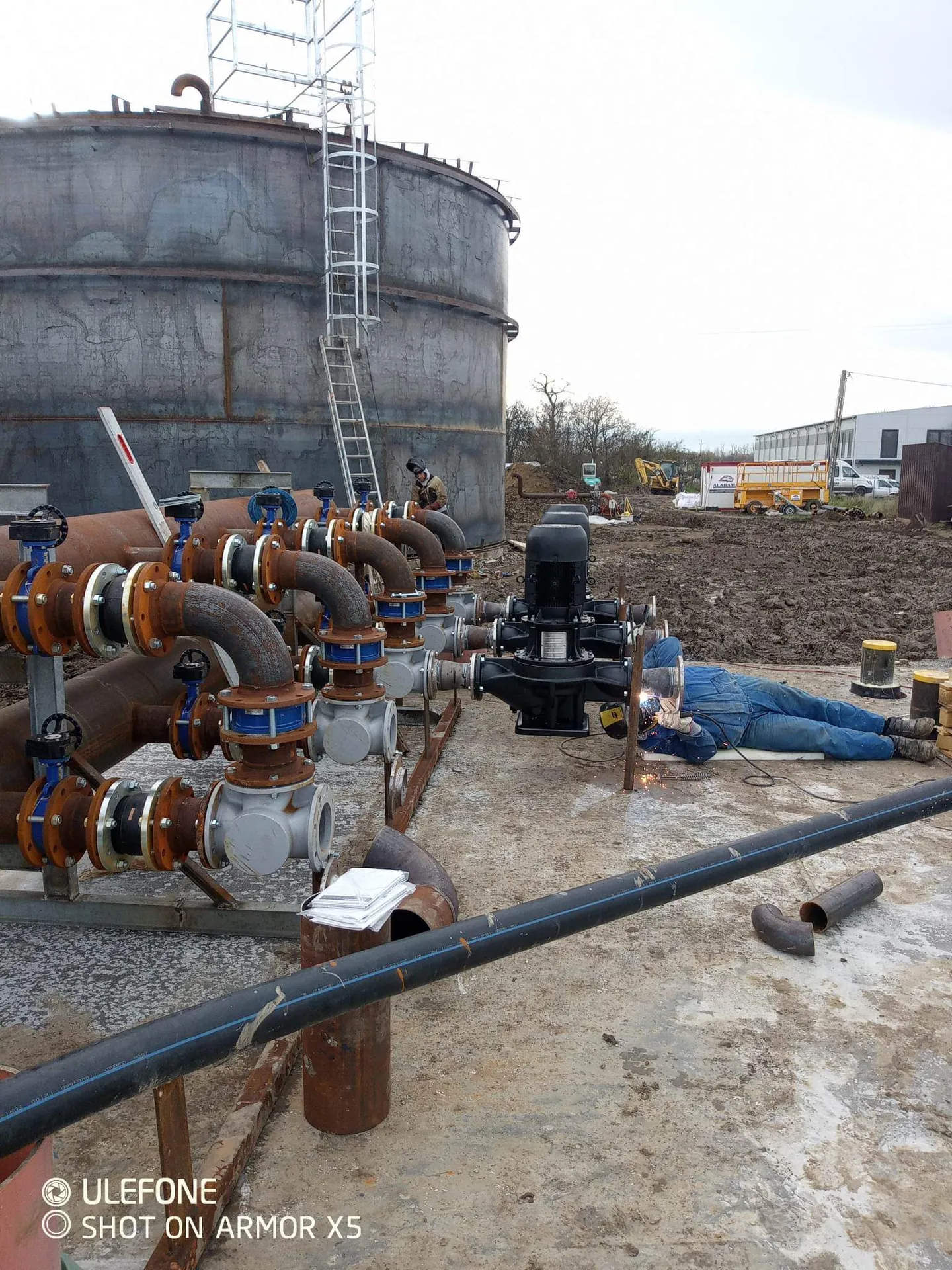
Multi-branch pipe assemblies and pump connections were installed beside the tank. The heating plant brings together the connections between storage and the supply pipework. Pumps move the water, while shut-off valves and other fittings provide control and connection points for each branch.
Larger-diameter pipe sections, bends and flanged fittings were assembled into connected units on site. The branches had to place each item of equipment on the correct pipe connection. Supports formed part of positioning the assemblies.
The installation also had to fit the working space around the tank. Equipment connections, shut-off valves and pipe routes all affected how the units could be assembled and accessed afterwards.
Insulated steel pipeline for the heating supply
Our scope included laying the insulated steel pipeline supplying heat to the greenhouse and industrial-building complex. It connected system sections at different points on the site. The tank and heating plant thus formed part of a longer heat-distribution connection.
The inner steel pipe carries the water, with surrounding layers providing thermal insulation and external protection. Site joints therefore require both the water connection and continuity of the outer layers. The route and end connections determine where the pipeline meets the mechanical equipment.
Straight lengths, risers, changes of direction and end connections each require installation work. These connections link the tank and site equipment to the systems using the heat, bringing the contracted heat-supply scope together.
The water and its surroundings are at different temperatures along the route. Pipe insulation reduces that heat transfer across the site connection. Tank insulation and pipe insulation support the same heat-supply purpose at different parts of the system.
Thermal insulation and external metal cladding
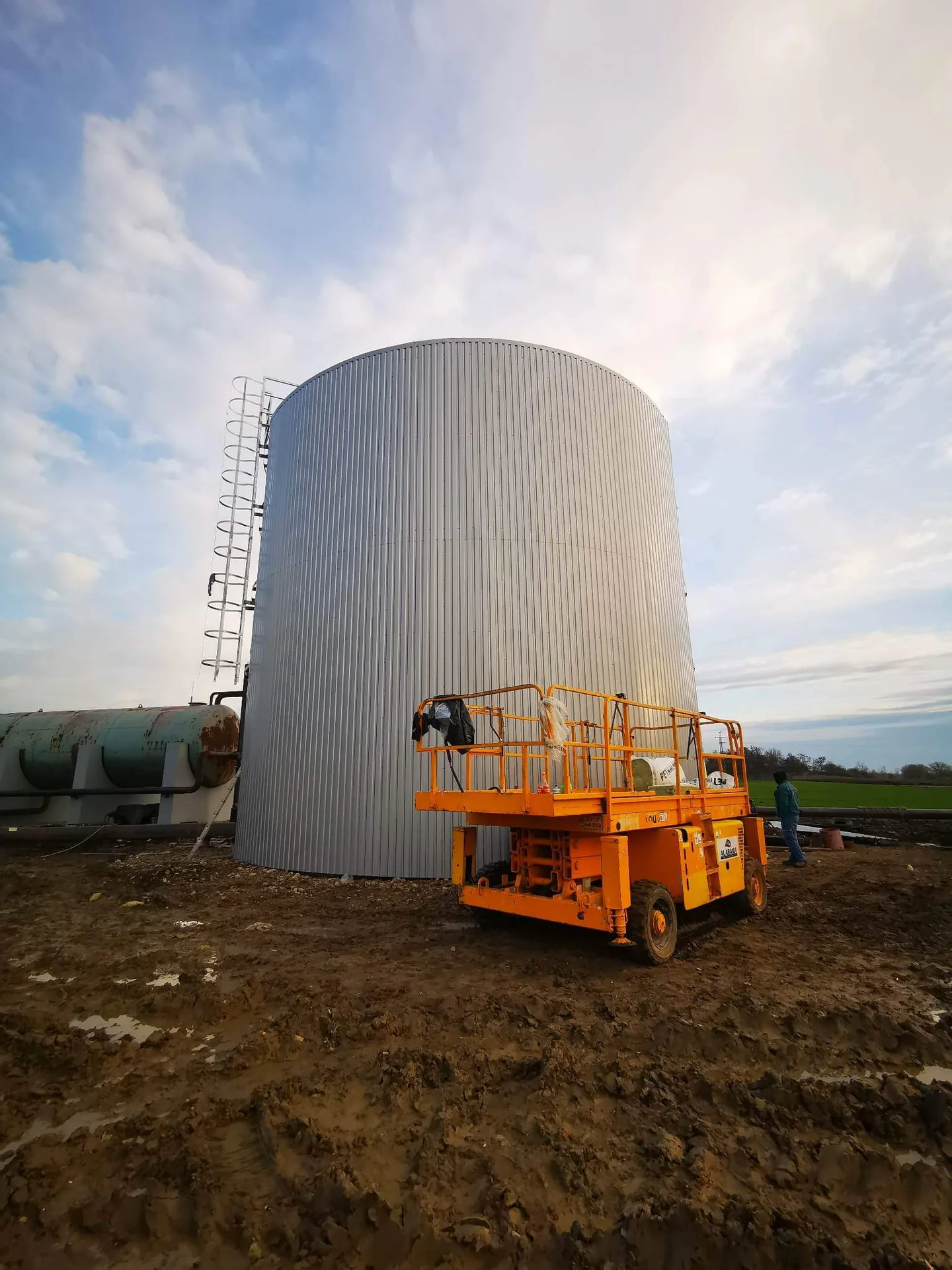
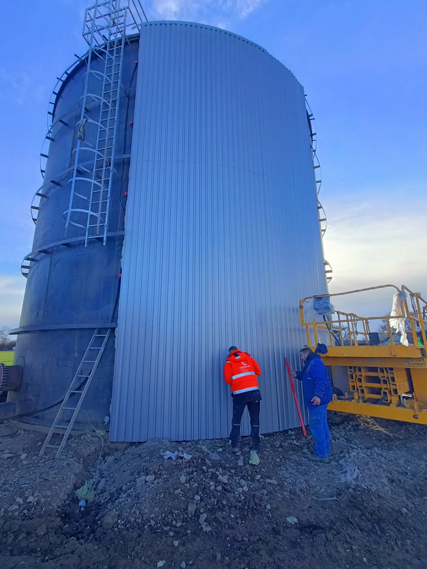
Thermal insulation and sheet-metal cladding were installed outside the full-height steel tank. Vertical sheets cover the wall. Installation had to follow the tank circumference, the arrangement of adjoining sheets and the area around the access ladder.
Cladding progressed around the tank in successive stages. The partly clad and later clad states distinguish steel structure construction from completion of the external layers. The work required access to different heights along the wall.
The external sheets protect the insulation from the weather and give the tank a consistent finish. Connections, ladder edges and cladding terminations needed attention as well as the large areas of wall.
At the access ladder, several components meet the curved tank surface. The cladding had to follow the shell while preserving the ladder’s function. Finishing therefore included these local junctions as well as the main wall areas, with aligned sheet strips and orderly edge details.
The result of the coordinated work
The full contracted thermal-water tank and associated mechanical scope was completed in Szentes. The insulated 1000 m³ tank, heating plant and supply pipeline were connected as one system. The work required coordination between steel construction and site mechanical installation.
Each part has a connected role: the tank stores water, the mechanical equipment moves and distributes it, and the pipeline reaches the complex being heated. Insulation contributes to the thermal design of both storage and distribution.
Our work stages show the process from early plate assembly through shell and roof construction to mechanical installation and external cladding. Together, these connected tasks delivered the heat-supply connection within our contracted scope.
Our work stages on the thermal-water tank in Szentes