Alabama Szer Kft.
Project implemented
Mechanical equipment room and horticultural heat supply near Üllés–Forráskút
In the Üllés–Forráskút area, we constructed a mechanical equipment room, a booster-pump circuit and a greenhouse heating substation.
- Year completed
- 2024
- Site
- Üllés és Forráskút
- Work completed
- Engineering and gardening pipework systems
The Trivega Kft. A new steel frame engine house and related gardening engineering system have been developed for your order Üllés–Forráskút in its region. The self-undertaking was the construction of construction works, the construction of the pre-pressure pump circuit, the laying of preinsulated underground pipes, and the work of the plant's subthermal center. In the investment that took place in 2024, construction of the new engine house and the related pipework systems were a joint task.
Engineering and pipework systems for horticultural heat supply
The Trivega Kft. In its 2024 investment, a new engine house was built in Seats, with a related pre-pressure pump circuit, pre-insulated underground wires and plant-house subthermal work. The Alabama Szer Kft. has carried out tasks related to the construction of the building and the construction of horticultural engineering. Commitment Üllés és Forráskút affected its area by linking machine house and network workplaces.
The engine room is the location of the equipment for the heat supply of cultivation. A new building for the installation of heating hot water pumps, connected pipes and related fittings is in the project. The investment therefore included the construction and mechanical engineering tasks. The building has created the location of the machinery units and the pipelines have linked them to further points in the gardening heat supply.
97 sq m steel frame engine room
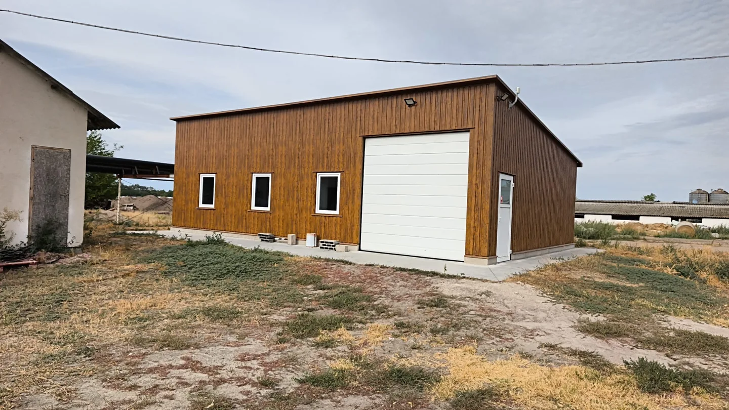
The design of the seating machine housing shall represent an external dimension of 8,05 × 12,05 m. The built-in floor area in the technical specifications is 97,00 m ² and the machinery house has a space of 94,01 m ². The ground-floor steel-frame building was located next to the existing economic buildings of the site and the steel water tank. The internal space is intended to accommodate pumps and their associated pipelines.
The plant room, covering nearly one hundred square metres, provides operational space suited to its mechanical function. Besides the equipment and pipe connections, the shared room also needed space for installation access. The wide entrance allows larger units to be moved, while the side windows provide natural light. The exterior and interior arrangement therefore had to be considered together with the site’s mechanical equipment.
Construction works for engineering
The construction of the new engine room was also associated with the construction of the building master's tasks. The steel support frame was accompanied by concrete and foundation work, and the interior was provided with a smooth concrete floor. The export tasks included the preparation of concrete anchors for underground piping. These construction elements were connected to the reception structures of the building and pipework systems.
The space requirements for mechanical equipment are already present when building the building. The entry points for the floor, the steel frame and the pipe connections are in the same space, and therefore the relationship between the construction and construction works had to be reviewed together. In the seating design, the creation of the new engine room and the construction of the machinery units in it created a matching task package. The receiving part of the building provided a physical framework for subsequent installation.
Steel support and trapezoidal coating
The engine room is equipped with a light structure: the load-bearing frame of the building is provided by steel elements, the outer walls and the roof are limited by trapeze plate. On the finished outer surface there are brown tiles and white arrows. The ground floor building captures a separate mechanical room and the large gate gives access to the movement of equipment and installation units.
The construction of the steel frame and the plate cover is related construction work. The position of the support device determines the connections of the wall and roof surfaces and the design of the openings is adapted to the use of the engine room. On the inside, the steel roof structure and the mechanical units already placed are visible in common space. The construction and engineering design of the engine room has created the conditions of the same operational function.
Construction of a booster-pump circuit
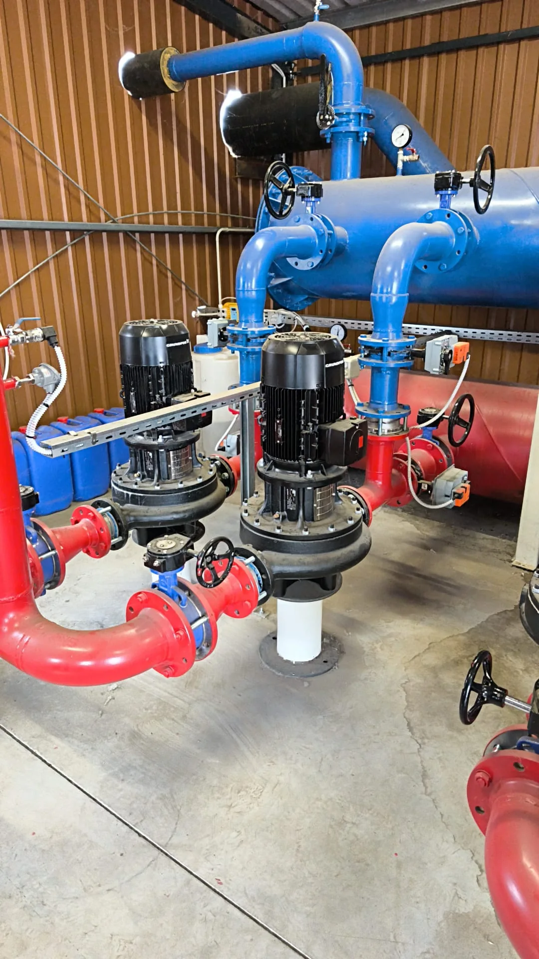
One of the main elements of the mechanical part was the pressure pump circuit. The pipes, fittings and common lines connected to the pumps are located in the engine room. The task of the machinery units is to move heating hot water and therefore the arrangement of equipment and pipework systems had to be developed as a common system. In addition to setting up the individual machines, the connection between them and the wires was also affected.
In the vicinity of the pump circuit, it is important to have access to the equipment and the mounting of connections. The pipes should also be compatible with the network outside the engine room, so the internal layout and the external connection define the site task together. The pre-pressure pump circuit in the seat work is designed as part of a system connecting the engine room to the associated heat supply points.
Dividing collectors and painted pipelines
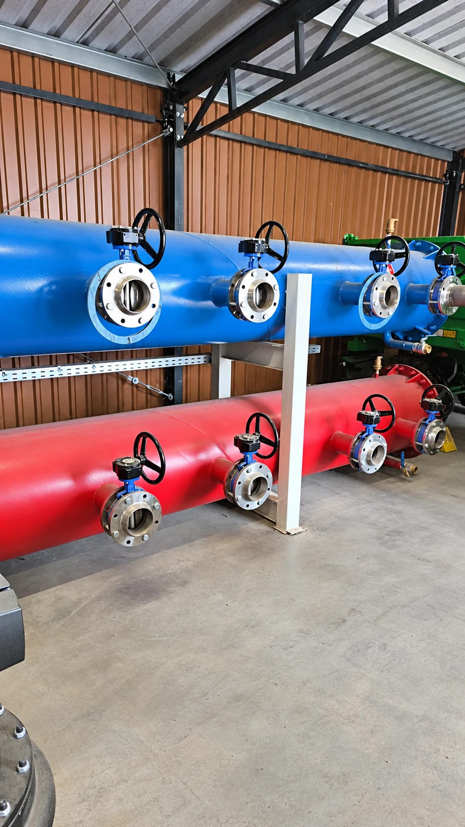
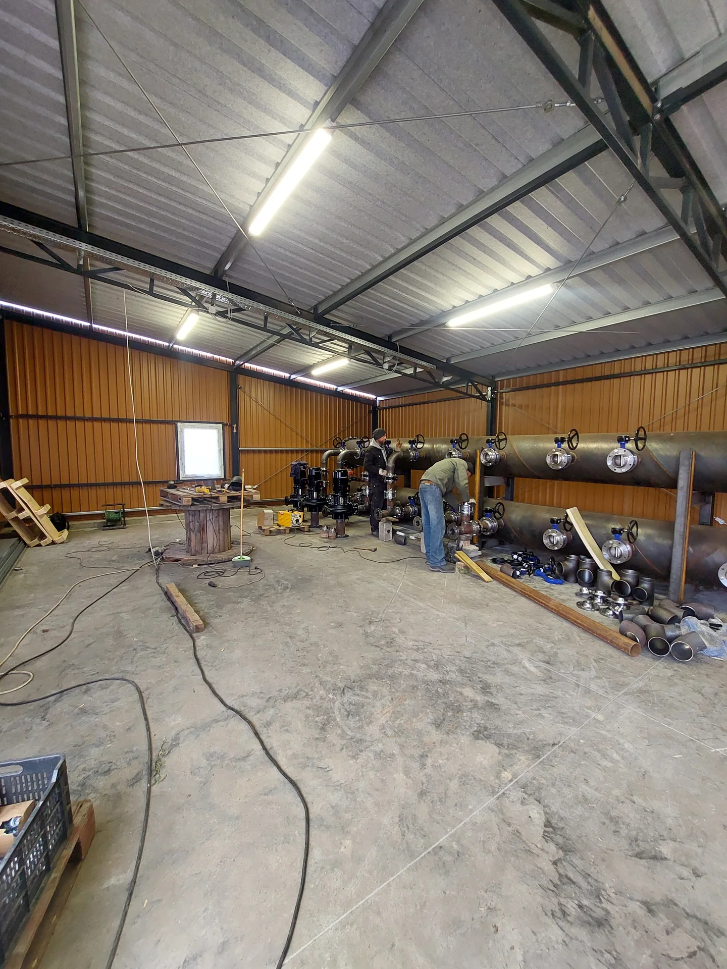
Inside the engine room there are larger size divisions and connecting pipes. Pump and hand assemblies appear along each branch. The wires painted red and blue are the key elements of the machine-house design and the same assembly can be made on the installation stage.
The dealer-collector is the mechanical unit that combines several tubes. The combined arrangement of the wires and fittings associated with it provides a pipework system connection between the equipment. In the construction, the location of the connections, the installation direction of the elements and the space for access had to be managed together. The assembled machinery units are consistent with the long order of the room and the surrounding sections continue towards the external line.
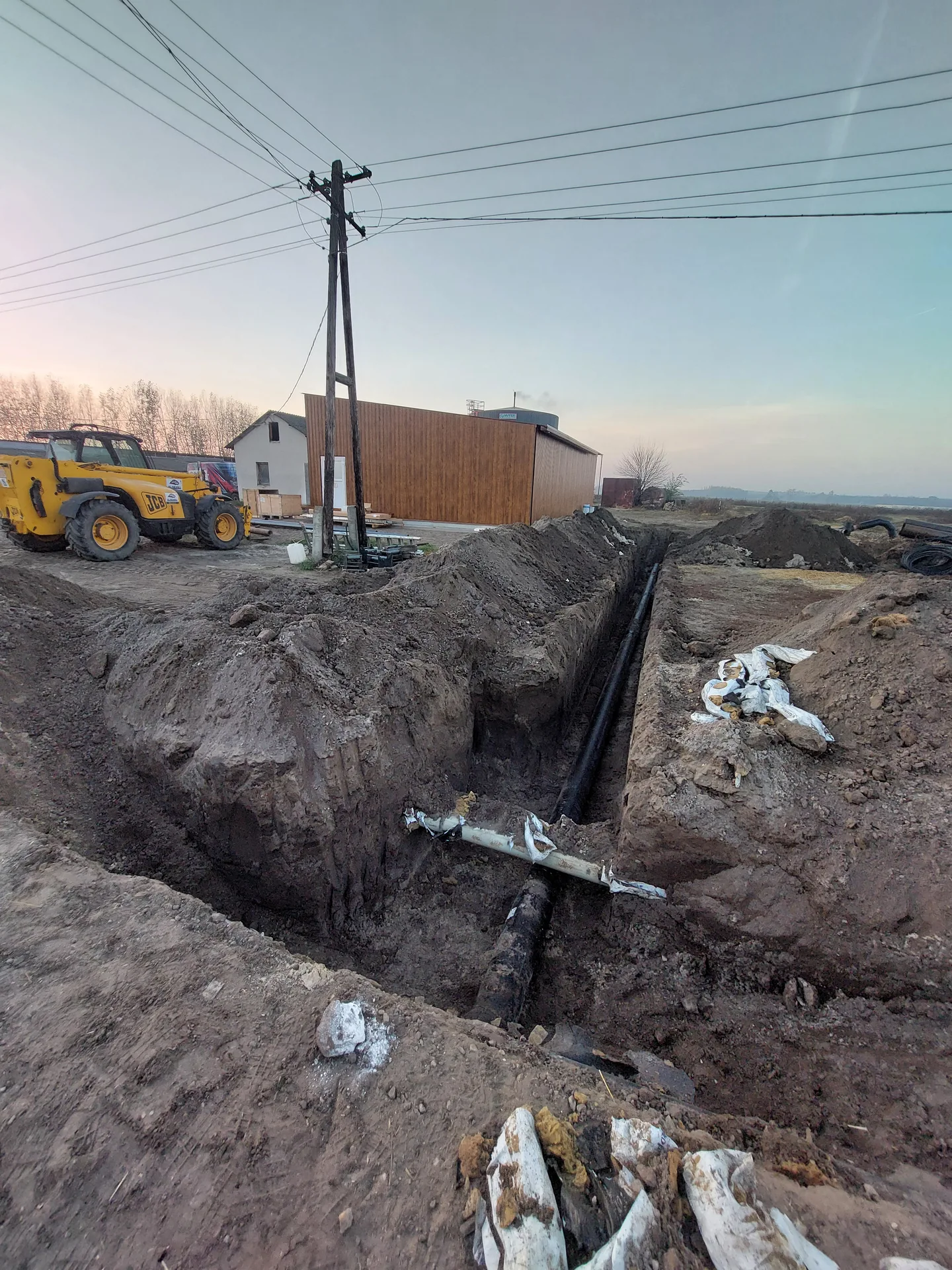
Preinsulated wires on underground track
The construction of pre-insulated underground pipelines was connected to the pump circuit. The normal track is the seating and in Forráskút It's affected locations. The pipeline lay was carried out outside the engine room and therefore the movement of tube materials and the approach to each assembly point had to be adapted to the real on-site environment. The work photo shows the open piping and the mounted wire section.
The pre-insulated wire creates a connection between the points of heat supply that are located further away. The tube body, insulation and cloak are part of the same incorporation tube and the network is connected by straight sections and associated connections. Working in the engine room was a joint task of fitting reception points and underground wiring sections. The interior assembly and external pipework systems thus continued in the same mechanical system.
Plant-house subthermal work
The undertaking also included the construction of a subthermal centre within the greenhouses. The subheat centre is the mechanical point associated with the meeting of the heat transport and the heating system in the greenhouse. Therefore, the construction of pipe connections and related mechanical elements between the external line and the internal greenhouse network was part of the task.
The engine room, the pre-pressure pump circuit and the subheat centre are located in different locations, yet they are connected to the heat supply. They were connected by the pipeline and therefore the construction work had to be done at several points in the network. On the seat Forráskút This is the interconnected task of own engineering in investment. The lines between the pump units and the plant connection are elements of the same heat supply connection.
Installation and access in Engineering
The internal layout of the engine room is determined by the space requirements of pumps, common lines and related fittings. The equipment shall be provided on several sides for on-the-spot installation and for subsequent maintenance shall also require access space. The layout of the building and the large gate opening together with the installation of the mechanical units provide a framework for the use of the operating space.
In the common machinery room, the pipework systems were operated together with the floor, the support structure and the arrows. The arrangement of pump branches, larger divisions and connecting wires was adapted to the same internal space. The relationship between mechanical and structural points in the construction therefore required continuous coordination on the spot. The engine room is filled with the installed equipment and the pipes leading to it with their own purpose.
Materials preparation from the workshop to the site
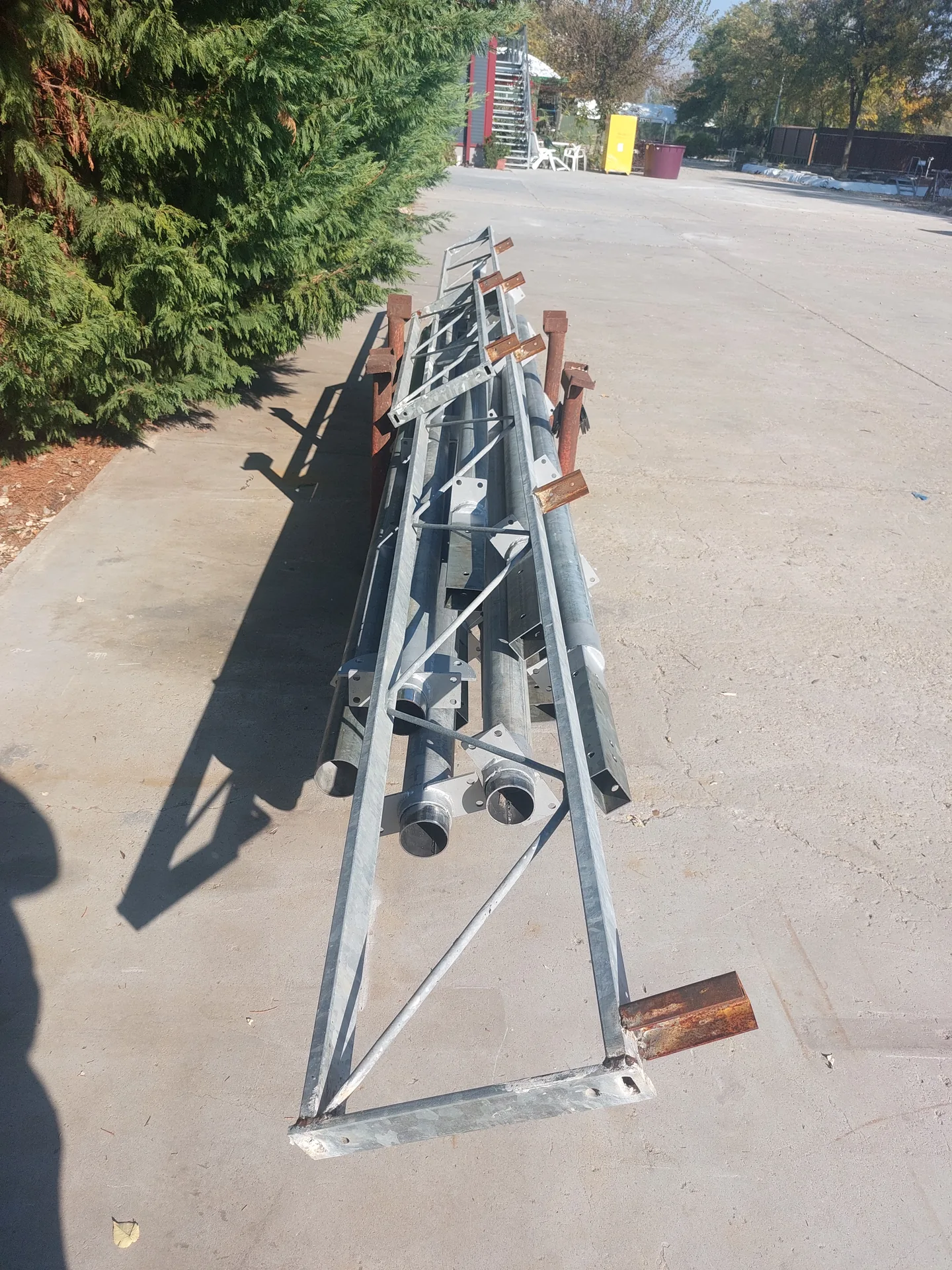
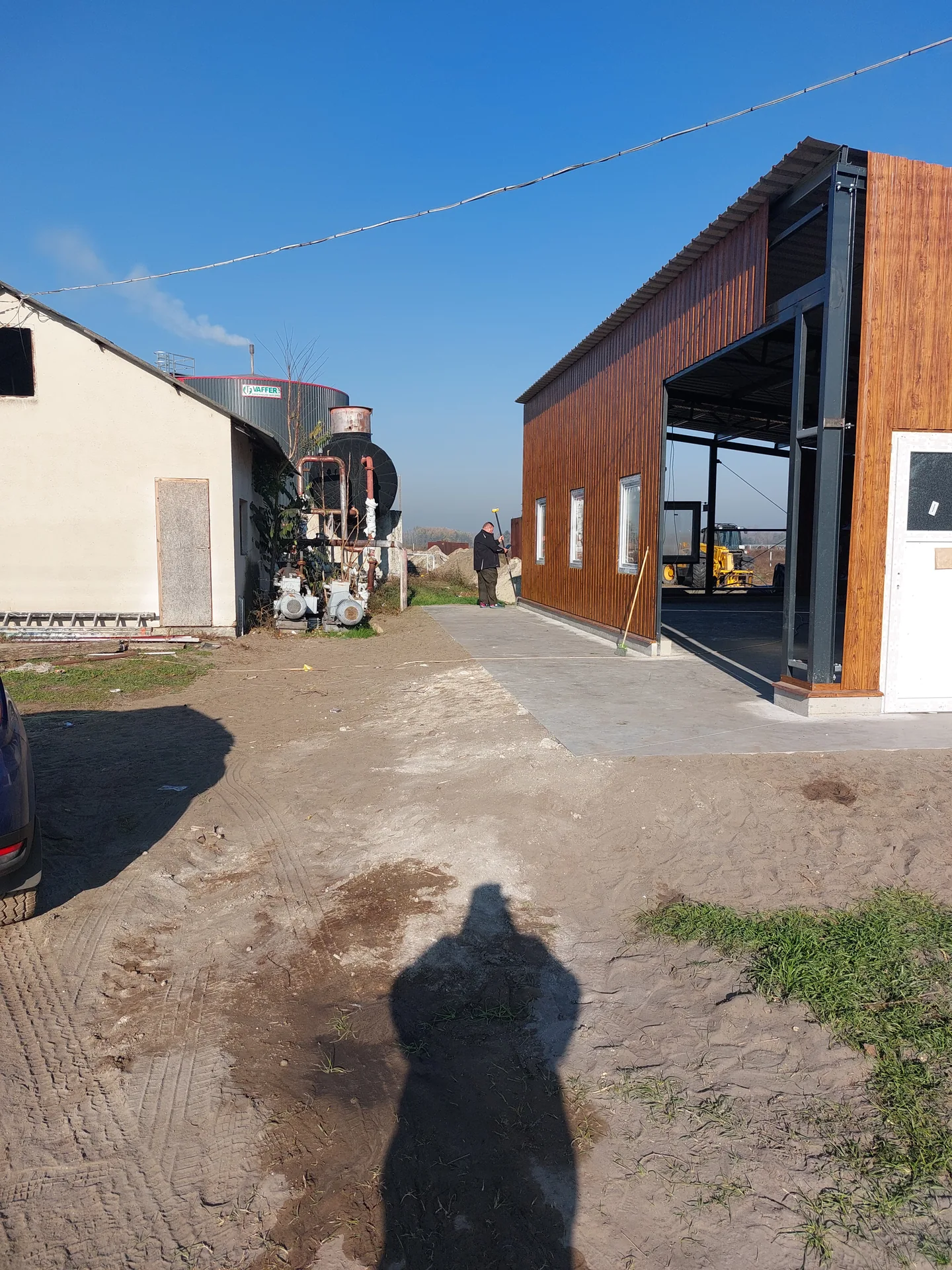
The machinery and pipework systems had to prepare steel elements, pipes and mechanical fittings.2024. In autumn work, the related frame components, the engine room installation status and the preparation pump group are displayed. The preparatory elements continued in the on-site assembly and were adapted to the condition of the building and the receiving network.
For the movement of machinery units and longer piping sections, a fitting area is required. The work area around the engine room, the interior access of the building and the external piping were therefore to be treated in relation to each other. The availability of materials and the location of the next installation shall be counted together in the on-site installation. The 2024 construction linked this work inside and outside the building.
Construction and engineering task in an investment
In order of Trivega, the construction work of the new engine house and the mechanical work related to the pump circuit, wiring, subheat centre formed two linked undertakings. The investment had to create both the location of the equipment and the pipework systems connecting them. The Alabama Szer Kft. has carried out its own workplaces in full, coordinating the construction and installation tasks on the spot.
The new engine room was between existing buildings and heat supply units at the site. The pipework systems also connected to the track that continued beyond the site's borders, so the work has appeared in several areas of installation. The building of the engine room, the pre-pressure pump circuit, the pre-insulated pipes and the plant-housing subheat centre together provided the contents of the task package. The implementation meant linking these parts.
Gate opening and approach to machinery units
The layout of the engine room shows a gate door of three metres wide and three metres high. The large opening is linked to the movement of mechanical equipment and assembly units. The pumps, pipes and fittings in the building require adequate access at the time of installation. The gate connects the interior of the building to the external work area, so its location, along with the layout of the engine room, is significant.
In the facade design, white windows and separate front doors are also displayed next to the large gate. The windows are designed to access the building and use the interior, and the mechanical fittings are located in the common room. The link between the layout and the working function is therefore also reflected in the design of the openings.
The conditions for the installation of equipment in the construction of the seating machinery room had to be established together with construction work. The floor, the steel frame, the wall and the gate opening are part of the same operating space. The installation of the mechanical units was linked to this finished receiving environment.
Results of 2024 construction
Our own workhouses were made in 2024. The autumn footage shows the construction of the engine room and the mechanical installation conditions, and the end of the year the customer's closure has named both the new engine house and the related heat supply work. The outside view of the finished building already shows the brown hull and the white windows, and in the interior there are pumps and painted dividing lines.
The Trivega Seats Forráskút in its investment, Alabama Szer Kft. its construction and engineering operations were linked to a common heat supply task. The steel frame engine room, the pre-pressure pump circuit, the pre-insulated underground wires and the plant housing subthermal work were a coherent technical work. The result of the project was the construction of the new engineering building and the corresponding pipework systems units.
On-site and installation pictures of the construction